Medium-Frequency Transformers:
The Critical Enabler of High-Performance
Solid-State Transformers
Following our previous deep dive into solid-state transformers (SSTs), one component stands out as both an enabler and a bottleneck for their large-scale deployment: the medium-frequency transformer (MFT). Often less visible than power electronics, the MFT is nonetheless central to achieving compact, efficient, and scalable SST architectures.
What is a medium-frequency transformer and why does it matter?
A medium-frequency transformer operates typically in the range of a few kilohertz up to several tens of kilohertz, far above the 50 – 60 Hz of conventional grid transformers. This increase in frequency is not incidental – it is the key to dramatically reducing the size and weight of the transformer, which directly impacts the overall footprint and cost of SST systems.
At its core, the MFT performs the same essential function as any transformer: it steps voltage up or down so power can be matched to the needs of the next stage in a converter or load and provides galvanic isolation between electrical circuits. This isolation is critical for safety, system protection and voltage adaptation in applications ranging from DC grids, electric vehicle charging infrastructure to data centres, rail systems, and industrial electrification.
In SST architectures, galvanic isolation must be maintained while operating under higher switching frequencies and increasingly demanding electrical conditions. This makes designing MFTs especially challenging as electrical stress, thermal behaviour, material properties, and converter interactions must all be mastered simultaneously.
The design challenges of medium-frequency transformers
The first challenge lies in increasing power. Higher power levels require larger magnetic cores and windings – the active components of the transformer. However, unlike conventional transformers, MFTs must balance thermal management and electromagnetic performance with the objective of drastically reducing the equipment's size. As the components' size increase, design complexity grows exponentially, making optimisation increasingly difficult.
The second major challenge is voltage. Moving to medium- and high-voltage levels introduces stringent requirements for the MFT's insulation. It must achieve high dielectric robustness to be able to withstand medium-frequency electrical stress, which differs significantly from traditional low-frequency conditions.
The key element of MFT design: insulation!
Medium frequency transformer insulation must deal with tougher conditions than in a standard 50 Hz design. The active components are often packed into a smaller space, which creates stronger electric stress in certain areas. Power electronics also produce very fast voltage changes which the insulation must be able to withstand.
The electrical stress in an MFT is also less predictable than in normal sinusoidal operation, with partial discharge activity tending to increase as the medium-frequency waveform becomes more aggressive. In addition, the insulation's reliability must be considered from the outset, as the intrinsic ageing of dielectric materials can accelerate under medium-frequency conditions.
Several insulation strategies exist, but each comes with its own trade-off…
Air insulation: simple & reliable but leads to bulky designs
Air insulation is a well-understood, easily implemented insulation solution. Air-insulated MFT designs can achieve high-frequency, high-voltage conversion but the reduction in size compared to traditional equipment is less drastic than in oil or solid insulation designs.
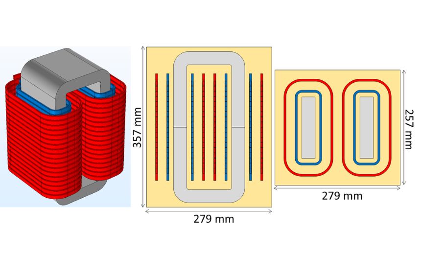
For2ensics: Paving the way for efficient, compact medium voltage DC/DC converters using air-insulation
The For2ensics project is advancing high-frequency, high-voltage conversion by developing a full-scale demonstrator which reduces converter size and cost while maintaining efficiency. SuperGrid Institute developed a 10 kV air-insulated MFT for the project which offers a meaningful improvement over conventional low-frequency transformers and serves as a solid proof of concept for MVDC power conversion. Enhanced by advanced materials for the magnetic core and windings, the demonstrator confirms that medium-frequency, high-voltage operation is both technically feasible and suitable for industrial applications, bridging the gap between laboratory research and deployment. That being said, air-insulation may present some limitations for reaching higher voltage levels.
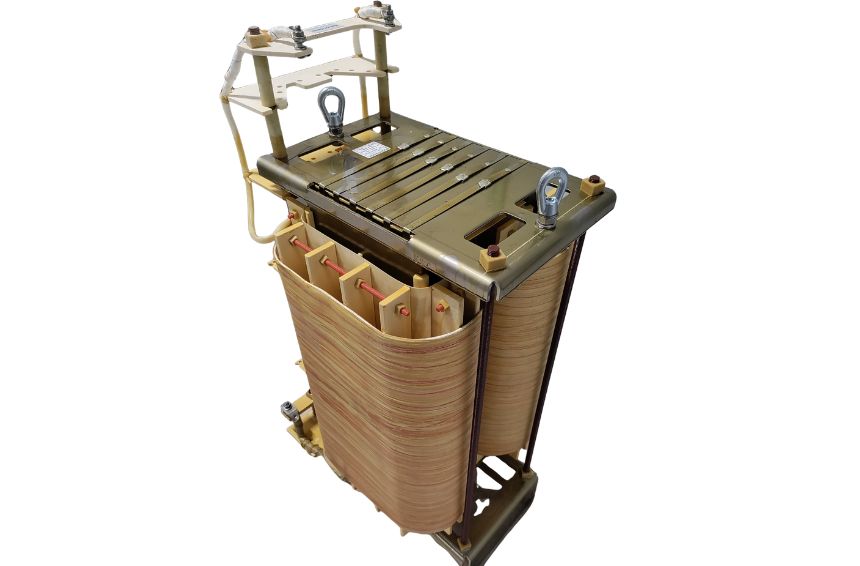
250 kVA 10 kHz | 12 kV class air insulated | Bidirectional DC-SST
Oil insulation: highly performant but logistically complex
Oil insulation offers excellent dielectric strength & very effective cooling, which helps manage the higher electrical and thermal stresses created by compact designs. However, this method comes with a bulky oil tank and sealing system and more demanding maintenance requirements as the active components are difficult to access. Oil insulation offers a solution when robustness and heat management matter more than extreme compactness and when higher voltage levels are targeted.
OPHELIA: Unlocking high voltage and power with oil insulation
The OPHELIA project is France’s first MVDC linear photovoltaic power plant demonstrator. As part of the project, SuperGrid Institute delivered three 250 kW 10 kV DC Solid-State Transformers each containing an oil-insulated MFT. The oil-filled MFT design operates at 10 kV, with the potential to reach up to 25 kV – levels that approach the practical limits of air and solid insulation systems. By integrating advanced materials for the active components and optimising thermal and dielectric performance, the MFTs developed for OPHELIA demonstrate a viable route toward high-power SST applications.
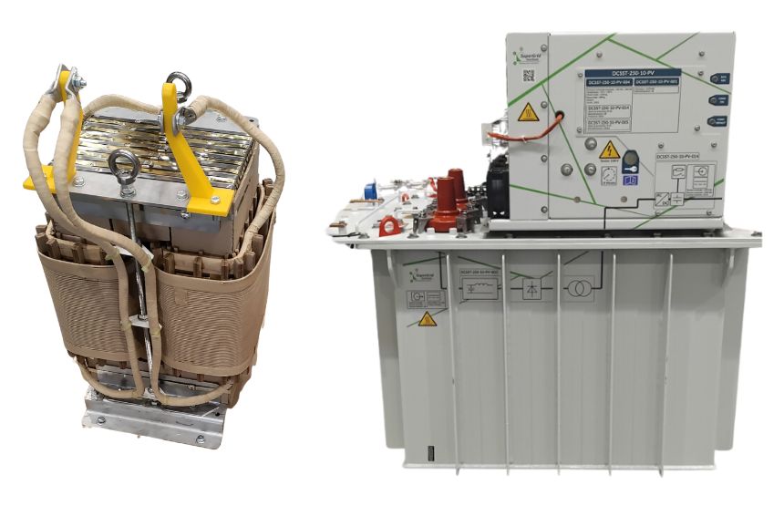
250 kVA 10 kHz | 12 kV class oil insulated | Unidirectional DC-SST
Solid insulation: allows compact designs but requires very specific expertise
Solid insulation allows for the most compact designs out of the three insulation solutions presented. However, developing a substance that can withstand the acute stresses produced by medium frequency transformation requires a keen expertise in material properties and advanced manufacturing processes.
ForCast: compact design at high frequency with solid insulation
The ForCast project aimed to produce a compact, high-frequency MFT operating at 40 kHz, with voltage levels up to 11 kV. The challenge: achieving high power density without compromising insulation integrity. SuperGrid Institute drew on its combined expertise in MFT design & material development to produce an encapsulated isolation transformer using resin casting – an approach which ensures robust and reliable insulation while enabling a compact design. By combining advanced materials with a precise control over the core and winding designs, the end product provided significantly improved power density compared to conventional designs.
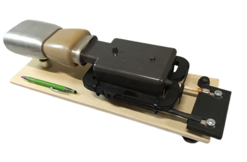
25 kVA 40 kHz | 12 kV insulation class– dry insulation | Modular SST application
The choice of insulation is not a standalone design decision: it shapes the transformer's size, performance, reliability, and overall integration strategy. The context in which the MFT is used also imposes stringent design requirements.
Integrating medium frequency transformers into power electronics: the end of siloed design
Unlike conventional transformers, MFTs are deeply embedded within power electronic systems, meaning their behaviour is shaped directly by the converter's topology, switching strategy, voltage & current waveforms, and control algorithms. In return, the transformer influences system efficiency, losses and even control stability.
This mutual dependency makes a co-design approach essential, with the transformer and converter developed together from the outset. System-level demonstrators have shown that validating the MFT in its operational environment is crucial to ensure realistic efficiency, controlled electrical stress and compatibility with industrial applications.
Providing practical tools for MFT design advancement
At SuperGrid Institute, we have developed a versatile, accurate tool for designing the active parts of MFTs. SUITED uses converter waveforms as inputs and rapidly evaluates key performance indicators such as size, weight, efficiency, losses and temperature, while covering the main medium-frequency technologies, from structure and magnetic core to conductors, insulation and cooling.
Thanks to fast analytic models, SUITED can explore around one million designs in a minute, helping identify the best technology choices for your MFT before fine-tuning the final design with FEM tools such as ANSYS or COMSOL.
SUITED design tool outcomes
Advancing SST technology through MFT innovation
As DC networks expand and applications demand higher efficiency, compactness and flexibility, the role of SSTs, and their integrated MFTs, will only become more critical.
SuperGrid Institute is uniquely positioned at the intersection of power electronics, materials science, and high-voltage engineering. Our integrated approach allows us to address the full spectrum of MFT challenges, from fundamental research to system-level validation.
Through projects such as ForCast, For2ensics, and OPHELIA, we are unlocking new performance levels for MFTs and delivering practical solutions that bring SST technology closer to large-scale deployment. In doing so, we are contributing to building more efficient, resilient and sustainable electrical infrastructures – where medium-frequency transformers are no longer a limitation, but a key enabler of progress.
What’s next: Exploring the extent of possible SST applications
In our previous articles, we looked at the role of the solid-state transformer, its components and key advantages. Now, with a better understanding of the technological elements that make up an SST, it's time to turn our attention to the applications where SSTs will come into their own. From MVDC distribution architectures to EV charging structures and data centres, the possibilities are vast.
Keep a look out for our next article to learn about the precise situations where SSTs will prove themselves as an enabling technology for future smart, adaptive grids.